ON7MV Receive-Beverage Project
The receive-Beverage project was developed as a complementary low-band receiving system beside the existing nine-element RX9 circle array. The aim is not to replace the RX9, but to provide additional directional options, different noise responses and longer end-fire apertures on 160 and 80 metres.
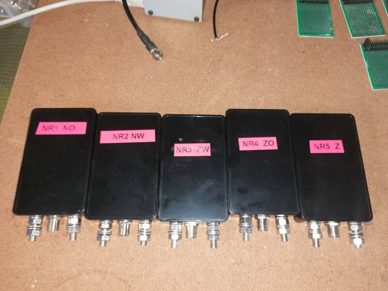
The planning evolved toward five receive wires. Both BOG arrangements and very-low Beverages, generally around 30-50 cm above ground, were considered. The final choice for each direction will depend on available land, wire length, soil conditions and the practical ability to maintain identical and weather-resistant end networks.
The principal design decisions are:
- Use non-inductive selectable termination resistors rather than assuming one universal value.
- Prepare a field-test range from approximately 200 to 447 ohms, with resistors of each selected value and at least 2 W dissipation.
- Use a simple galvanically isolated receive transformer instead of a complicated tapped network; the leading concept is a 2:5 turns ratio on a BN-73-202 binocular core.
- Treat common-mode isolation as a first-class design requirement, using a feed-point choke and additional station-entry suppression where needed.
- Use surge components such as neon lamps and gas-discharge devices as secondary protection, not as substitutes for grounding, disconnecting and TX interlocking.
- Ground or otherwise positively control unused receive wires; do not leave long conductors floating during transmission.
- Integrate the wire system with the existing RX9 and station switching so that all receiving systems are safely shorted or disconnected during TX.
No final field values for termination resistance, transformer response, choke impedance, front-to-back ratio or signal-to-noise improvement have yet been established. The present status is therefore best described as a well-developed construction and measurement plan that is ready for controlled field trials.
Development history and reason for the project
The RX9 circle array already provides eight electronically switched directions and a highly controlled low-band receiving pattern. The receive-wire project arose because a long travelling-wave antenna can react differently to local noise, arrival angle and nearby structures. A Beverage or BOG may therefore copy weak SSB signals that are difficult on the transmit antennas or may provide a useful alternative when one RX9 direction is affected by local noise.
The project was never intended as a single generic “Beverage.” The discussion covered multiple wires, different azimuths, BOG and elevated-low versions, selectable terminations, transformer matching, common-mode chokes, protection and switching. This broader approach is necessary because the optimum solution depends strongly on the actual soil and field layout at Vladslo.
The planning sequence was approximately:
- Consider several receive wires for the DX directions.
- Compare BOG construction with a wire held roughly 30-50 cm above ground.
- Determine a practical range of non-inductive termination resistances rather than purchasing only one value.
- Choose a simple broadband transformer concept.
- Plan strong common-mode suppression and lightning/static protection.
- Integrate the wires with the existing RX9, grounding system and TX interlock.
- Defer the final resistor, choke and length decisions until real field measurements are available.
Role beside the RX9 array
The RX9 and the receive wires solve related but not identical problems. The RX9 is a compact electronically phased array with rapid eight-direction switching. A Beverage or BOG is a long end-fire travelling-wave antenna with a pattern determined by wire length, ground coupling, termination and feed-point isolation.
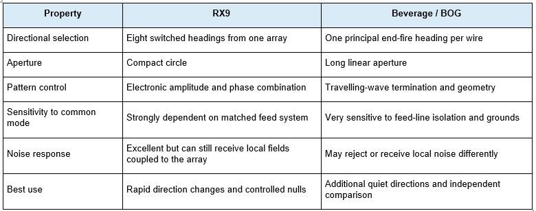
The practical advantage of owning both systems is diversity. A signal that is only marginally readable on one antenna may be clearer on the other because the wanted signal and local noise do not change by the same amount.
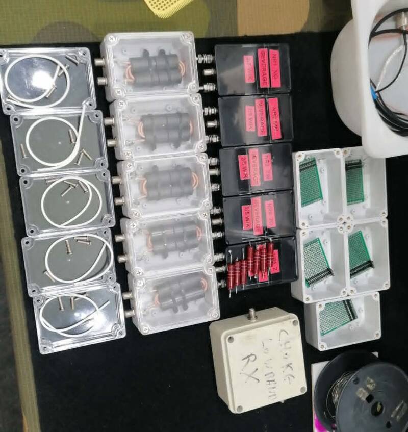
Complete receive-wire signal path
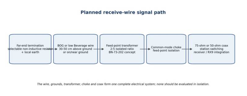
The complete receiving path must be treated as one system. A good wire can be spoiled by a poor ground, an inappropriate termination, transformer loss, feed-line common mode, or switching that leaves unused conductors floating.
BOG and very-low Beverage options
Two physical implementations were considered. The first is a true or near-true BOG, with the conductor on or extremely close to the soil. The second is a very-low Beverage held roughly 30-50 cm above ground. Both are electrically close to the ground and are expected to have lower output than a conventional higher Beverage, but they may fit the available land and agricultural use more easily.

Far-end termination resistance
The far-end termination is one of the most important adjustable parameters. Its purpose is to absorb the travelling wave and reduce reflection from the end of the wire. The optimum resistance is not a universal number; it depends on wire height, ground conductivity, soil moisture, wire length and frequency.
The agreed procurement and test concept was to use non-inductive resistors over a broad practical range:
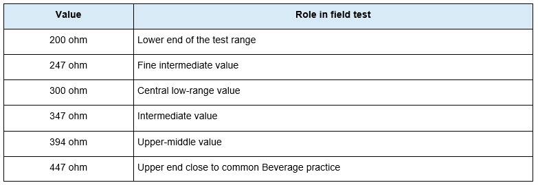
The planned purchase quantity was ten pieces of each value, with a minimum dissipation rating of 2 W and a non-inductive construction. The power rating is not required for normal received RF power; it provides physical robustness and some margin against static and transient energy. It is not a lightning rating.
The resistor should be selected by measurement, not by SWR. The preferred value is the one that gives the best useful directivity, stable noise performance and repeatability over the intended band. A resistor that produces the deepest single null on one frequency is not necessarily the best broadband choice.
Far-end and feed-point grounding
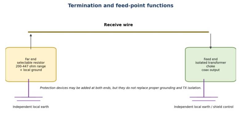
Both ends require grounding. The far-end ground completes the termination circuit. The feed-end ground and transformer arrangement control the return path seen by the antenna. Poor or inconsistent ground connections can change both amplitude and directionality.
- Use short, mechanically secure and corrosion-resistant connections.
- Do not rely on an incidental metal fence or unknown buried conductor as the designed ground.
- Keep the resistor and protection components inside a weather-resistant enclosure.
- Document the ground rod or ground system used at every end because different arrangements can produce different optimum resistances.
- Recheck after long dry periods, heavy rain or winter conditions because soil coupling may change.
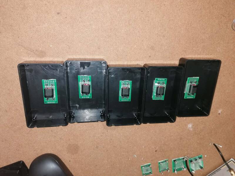
Feed-point transformer concept
The preferred design direction was a fixed, galvanically isolated 2:5 receive transformer on a BN-73-202 binocular ferrite core. This was chosen in preference to a complicated tapped unun because the transformer should remain constant while the far-end resistance is changed during optimisation.
A 2:5 turns ratio has an impedance ratio of:
(5 / 2)^2 = 6.25
Therefore, depending on the coax system used:
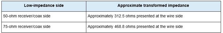
This does not mean that the wire is exactly 312 or 469 ohms. It means that the 2:5 transformer is a reasonable broadband compromise for common Beverage impedance levels. The field-selected termination remains the primary control of travelling-wave absorption.
Common-mode choke strategy
Common-mode current on the feed-line shield can destroy the intended Beverage pattern by making the coax part of the receiving antenna. For this reason, the choke is not an optional accessory. It is part of the antenna system.
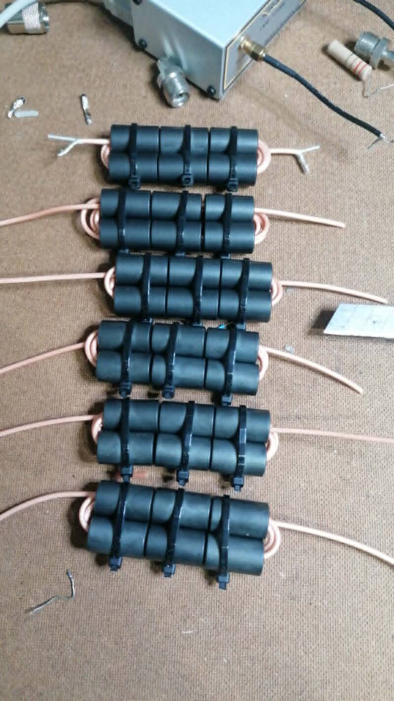
The intended choke locations are:
- Immediately at or directly after the feed-point transformer, to keep the outgoing coax shield from becoming the antenna return path.
- At the field or station entry where the receive coax joins the common switching and grounding system.
- Additional suppression near controllers or switching equipment only when measurements show that it is needed.
Static, surge and lightning protection
Long receive wires can accumulate static charge and can intercept large induced voltages from nearby lightning. Protection was therefore discussed at both the termination and feed ends.
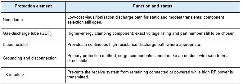
Protection devices should be placed so that a discharge does not have to travel through the transformer winding or station switching before reaching ground. All outdoor enclosures should permit drainage and should not trap condensation.
TX switching and unused-wire control
The station already follows a conservative RX/TX philosophy: receiving systems are shorted or grounded during transmission and receive DC is removed. The Beverage/BOG system should use the same logic.
- Ground or short the receiver side of every unused wire during TX.
- Do not leave a long receive wire floating while transmitting on nearby antennas.
- Remove DC from any active switching, preamplifier or bias network in the receive-wire system during TX.
- Use break-before-make switching and verify the state with an ohmmeter before connecting the system to the station.
- Consider the maximum station power and near-field coupling even though the receive wire itself is not intended to transmit.
The purpose is both protection and pattern stability. A floating unused wire can re-radiate or couple into the selected antenna, and a partially connected feed line can carry RF into the shack.
Integration with the station grounding and RX9
The receive-wire system must coexist with the RX9, transmit vertical arrays, control cables and the single-point station ground. Integration should minimise unintended current loops while still providing a safe DC and lightning reference.
- Route each receive coax in a documented and repeatable way; avoid large loops and close parallel runs with transmitting feed lines where possible.
- Keep local antenna grounds local at the feed and termination points; bond to the station system through the intended coax and protection architecture, not through random parallel conductors.
- Use the station entry as the controlled transition between outdoor grounds and the shack single-point ground.
- Compare the selected Beverage/BOG against every RX9 direction; the quieter antenna may vary by band, time and noise source.
- Test whether an unused receive wire changes the RX9 noise or pattern when left open, grounded or terminated. The safest default is a defined grounded state.
Bench checks before installation
- Continuity and insulation test of every coax, connector and switch path.
- DG8SAQ or FSH8 S21 measurement of the transformer from 1.8 to 7.1 MHz, including insertion loss and broad phase behaviour.
- Common-mode choke comparison using a repeatable fixture; record the frequency of any resonance.
- Confirm that the protection network does not load the receive path at the operating frequencies.
- Confirm DC isolation between wire side and coax side when galvanic isolation is intended.
Field termination sweep
Install one wire first and make the termination resistor easy to change. Test 200, 247, 300, 347, 394 and 447 ohms under the same soil and weather conditions. Do not compare values on different days without a reference signal because propagation and noise can change.
- Measure a stable ground-wave marker or local station from the forward direction.
- Measure from the reverse direction or use a second known source behind the antenna.
- Record forward level, reverse level, side level if available, and the local noise floor.
- Calculate front-to-back and signal-to-noise ratio; choose the best useful compromise over 160 and 80 m.
- Repeat after rainfall or a significant soil-moisture change before declaring the resistor final.
Comparison with the RX9
The key operational metric is not absolute signal level. It is whether the wanted signal becomes more readable. For every test signal, record:
- Received level on the best RX9 direction.
- Received level on the Beverage/BOG.
- Noise floor in the same receiver bandwidth.
- Calculated or observed S/N difference.
- Presence of local noise, impulsive noise or overload.
- Whether the result is repeatable on several signals and times.
Create Your Own Website With JouwWeb