Transformers
It’s looks all that simple if other people are making them.
I search the internet and there is only 1 explanation on you tube from VE6WZ.
That video shows how to make one for the rx amps.
I won’t make a video to show you how I did it but I will show you my results with the analyzer.
T1 Transformer
In the manual from YCCC they saying this.
Transformer T1 is 10 turns center-tapped using 9 inches of green 28 AWG and 9 inches of red 28 AWG. As in Figure 10, two passes form one turn. First wind 5 turns of the green wire through the core and then start a second winding of 5 turns with the red wire. Solder the end of the first 5 turns to the beginning of the second 5 turns to form the tap point. Solder the three transformer connections to the PCB. The center tap goes to the middle hole on the PCB. Because of the symmetry of the tapped transformer, it does not matter which ends of the transformer go to the outer holes.


This is how to measuring them like the manual says.
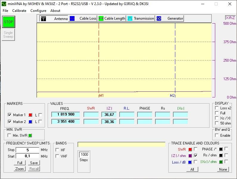
T1: Place a 75 ohm resistor across the entire winding of T1. Measure the impedance from the center tap to either end of T1. It should be about 18.75 ohms (1/4th of 75 ohms).
As you can see I am very close to the 18,75 Ohms.
The little deviation that I have would be normal because of my way of measuring.
T2 Transformer
In the manual from YCCC they saying this.
Transformers T2, T3, are T4 are wound as bifilar transformers. Figure 15 shows the bifilar winding technique. Take two wires (shown as red and green in the figure) in parallel and wind them through the binocular core, keeping them together as though they were a single wire. As in Figure 10, two passes form one turn.
Transformers T2 and T3 are each 7 bifilar turns using 13 inches of green 28 AWG and 13 inches of red AWG. The red and green wires will each make 7 complete turns through the core. The mounting holes on the PCB for T2 and T3 are labelled R, G, G, R. Take the wires from one end of the bifilar winding and solder the red wire to R and the green wire to the adjacent G hole. Take the wires from the other end of the bifilar winding and solder the red wire to R and the green wire to the adjacent G hole. Because of the symmetry of the bifilar winding, it does not matter which end of the winding is soldered to each pair of R and G holes.


This is how to measuring them like the manual says.
T2: You will need five 75 ohm resistors to perform this test. Make up two 37.5 ohm resistors by putting two 75 ohm resistors in parallel. There is a red wire and a green wire exiting each side of T2. On one side of T2, we’ll call the wires “green1” and “red1”. On the other side of T2, we’ll call the wires “green2” and “red2”. Make the following connections:
• Red2 to green1.
• One side of one 37.5 ohm resistor to red1. We’ll designate the other side of the 37.5 ohm resistor as “ground”.
• One side of the other 37.5 ohm resistor to green2 and the other side of the resistor to ground.
• The remaining 75 ohm resistor between green2 and red 1.
Now measure the impedance between green1 and ground. It should be about 18.75 ohms.
T3 Transformer
T3 is the same as T2 but the measuring are different


T3: This measurement is the same as T2 except the resistances are one half the values you used for T2. You will need four 75 ohm resistors to perform this test. Make up a 150 ohm resistor by putting two 75 ohm resistors in series. There is a red wire and a green wire exiting each side of T3. On one side of T3, we’ll call the wires “green1” and “red1”. On the other side of T3, we’ll call the wires “green2” and “red2”. Make the following connections:
• Red2 to green1.
• One side of one 75 ohm resistor to red1. We’ll designate the other side of the 75 ohm resistor as “ground”.
• One side of the other 75 ohm resistor to green2 and the other side of the resistor to ground.
• The 150 ohm resistor between green2 and red 1.
Now measure the impedance between green1 and ground. It should be about 37.5 ohms.
T4 Transformer
In the manual from YCCC they saying this.
Transformer T4 is 6 bifilar turns using 11 inches of green 28 AWG and 11 inches of red 28 AWG. The red and green wires will each make 6 complete turns through the core. The mounting holes on the PCB for T4 are labelled R, G, G, R. Take the wires from one end of the bifilar winding and solder the red wire to R and the green wire to the adjacent G hole. Take the wires from the other end of the bifilar winding and solder the red wire to R and the green wire to the adjacent G hole. Because of the symmetry of the bifilar winding, it does not matter which end of the winding is soldered to each pair of R and G holes.


T4: There is a red wire and a green wire exiting each side of T4. On one side of T4, we’ll call the wires “green1” and “red1”. On the other side of T4, we’ll call the wires “green2” and “red2”. Connect a 37.5 ohm resistor between green1 and green2. Measure the impedance across red1 and red 2. It should be about 37.5 ohms.
T5 Transformer
Transformer T5 is 7 turns, tapped at 5 turns above ground, using 9 inches of green (5 turns) 28 AWG and 3-5/8 inches of red (2 turns) 28 AWG. Solder the green and red wires together to form the tap connection. The mounting holes on the PCB for T5 are labelled GND, R/G, R. Solder the green wire to GND. Solder the tap (where red and green are joined) to R/G. Solder the red wire to R.

T5: Connect a 75 ohm resistor across the entire winding of T5. Measure the impedance between the tap (where the green and red wires connect together) and the green wire exiting T5. It should be about 37.5 ohms.
I know that my leads are too long and is have to remember that the clamps I use will have some deviation.
On the PCB of PI4CC they have a different labeling than on the one in the manual of YCCC
PI4CC they have 1A, 1B, 2A, 2B in the manual of YCCC the have labeled it R, G, G, R.
With the little knowledge I have I am close of what the manual says it should be.
My email is my call (at) telenet.be
Create Your Own Website With JouwWeb