Combining 2 RX9 circle
04/11/2021
Goal this year is to work E51 on 160m
Last year I only have had a few moment I could receive this station at my location the opening is very short so I have to improve my RX capabilities.
Did not find on line if this has been done before to combine 2 RX9 systems but if it is working with other antennas why wouldn't it work with this one.
First idea is to have one full 9RX and as a test a second one with only a three inline to 340° and 160°.
If this work is will set up a second 9RX.
Need to simulate it all first in Eznec to see what the distance of each other need to be.
The picture below is a first thought how I would combine the 2 and still can use them separate of each other.
The future will show if this will work, once it's built, I'll be sure to discuss this further here.

Making the coupling combiner
9/11/2021
My goal is to be able to use each RX9 separately and the two together, Again simple reason, First test will be each connected separately to see if I make RX2's antennas longer than RX1's to see what the change will be, Second test is to make the middle antenna a bit shorter than the rest, Reason would be "that" if you shorten it you could squeeze the backlobs even more.
You can only test this if you have 2 of those systems so that with a simple turn of a button you can switch between the 2 RX9's and hopefully be able to perceive the difference.

T1 and T2 are for combining the 2 RX9
T4 is for RX2 to go from 75hom's to 50 ohms
T3 is the same as T4 but for RX1.
The cores I am using are the same for the 9RX (YCCC manual)
The grounding is completely isolated from each other except the combined one.
Almost finished but wanted to test the mono ports here first.


This is the first reading of RX1 here the T3 is in use to go from 75ohm to 50 ohm.
This one above is from RX2 the same explanation as the other but here T4 is in use

Here I am going to measure the combined port, don't forget when you do the measurements that you have to connect a 75ohm resistor to the input ports (nr1 and 2)
I took the middle at the top as the combined , on the left in the photo is the RX1 and then on the right RX2.

Above the result of the measurement on the combined port.
If I would use the correct resistors, that measurement will remain more stable around 50 Ohm
Another test I did is to connect the combiner of RX9 (2) to the coupling combiner and on the 2nd input port a 75 ohm resistor.
The last thing I have to do is control this combiner at the same time with my coax switch (link) only for the middle port I have to take the 12Vdc from the RX switch so that the relays of the ombiner automatically get their voltage.
Tomorrow I'll try to fix this and then post the result here as usual.
12/11/2021
We are another day further, in the meantime a lot has already been done...
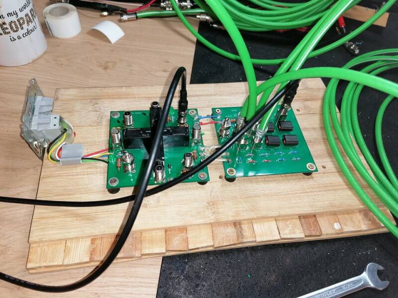
We have mounted the antenna preamps in a box, a simple built-in box.... as you can see in the pictures

yes i know i only need 3 but I will build the 5el version... anyway the first direction would be 340° and 160° the other I would take 25° and 205°
In the meantime also did some further tests with the coupling combiner...
So I wanted to switch this with my RX coax switch so that I don't have to lay more DC cables, on that RX coax switch each output has its 12Vdc so I will steal the 12v to operate the coupling combiner.


While I was at it, I applied the same for my FO0AAA loop, but that RX antenna is on the other RX switch.
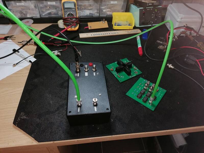
The black box on the left is the coupling combiner for the 2 9RX's
The aluminum box on the left of the black box is where all RX9's arrive both the mono version and the combined version, the aluminum box along the other is where the other RX systems arrive including a simple RX vertical a Coax loop and then that FO0AAA loop which also has a preamp so it need also 12Vdc.
I can now also switch this simultaneously with my RX switch..
The little black box on the end is te Bias T for the preamp of the FO0AAA loop..
The green coax on the left is the first RX9 already in use at this moment.
Next order is to put the 2nd RX9 in a waterproof box, the antennas are ordered from my wife's work, they had them in stock but didn't want to wait so they are going to bring them to my house.
I suspect that I can do the first tests by next week...
16/11/2021
Aluminum tubes have been delivered, this time they are a bit smaller in diameter.
we will see if this also works, for 5 antennas I have now paid 33 €


As a test I left the preamp outside for a few days to check whether this box is indeed waterproof and luckily for me it was.
Now that the antenna was so close to the shack I tested all my preamps and 1 was dead in the meantime it has already been repaired so that I now have 5 working preamps for my 5 el version.
When my garage cleaned up a bit I saw this old RJ45 built-in and thought I could use it to operate the 2nd RX there was also a reason it was somewhere because the back was no longer there.

Now we are and remain amateurs so why not just solder to it.....I then sprayed it with liquid plastic afterwards

The last tests and everything seems fine so we can put it in the much too big waterproof box but I still had that box and would be a shame to have to buy another one


Everything is ready to test in the meadow.
Field test
In the meantime only 3 el inline, I have to be patient for the 5 el version because that meadow is still partly used by the farmer.
The first three face 25° and 205° (approximately)
Are currently around 60m apart by that I mean between the first RX9 and then the 3 el version.
I haven't taken a picture of it yet because it still has to be moved according to eznec the distance should be 100m.
This set up to see if the system itself works perfectly compared to the first one and if my coupling combiner works also.
Eznec files will be post later on...

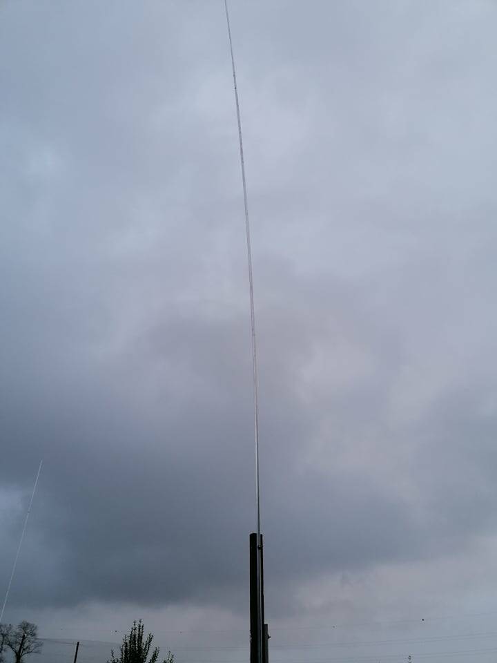
Thought I'll take a picture later but.... so I went outside especially in the rain to take some pictures.
So it is only a test set-up, you can see the field is not yet completely clear, so I have to wait until the first days when it starts to freeze and only then will the beets be removed
At the hedge you will see 2 small posts that is the 50m mark from the other RX 9 that is on the other meadow.
This morning I moved the other 9RX so that it was (about) 50 m from the shack.
Here you can clearly see that the meadow is still in use.
Sometimes I think grrrr get those things out neighbor on the other side I think many amateurs wish they could do this because there is already 1 on his meadow.
And i can just put 2, i can still place beverages in all directions as long as i want (which i wont do too much work)

Predictions eznec
Now I am treading on thin ice because my knowledge of eznec is not as it should be...
I hope I made everything right and that I didn't do anything stupid.
If anyone would like to do this for me let me know.
The normal RX9

Combined RX9 100m distance

Normal RX9
combined RX9


28/11/2021
The beets have been harvested and we have built everything up in the meantime.
Antennas have been replaced to the thicker version, my goal to save some money has not been successful.
Now, just like the first RX9, I use 2 aluminum tubes to make 1 antenna (4m, 1 of 22x1.5mm and 1 of 4m of 25x2mm).
There are also not 3 but 5 now, towards 340° and 160° and the other at 25° and 205°.
Right now after the first few days of testing it doesn't seem to be working as it should.
The output of RX2 is significantly lower than the output of RX1.
I also notice that the noise on RX2 is also lower, which can be explained by the fact that the output signal is also lower.
If I use them in combination I do receive but I notice no gain and actually some loss compared to the monoband version.
More tests to be taken, My first is to get both output signals equal of the mono version.
In the manual of YCCC they say that you can increase the output a bit if you make the antennas longer.
So this will be the first thing I'm going to do.
With such a large system it is true that you cannot quickly adjust everything quickly.
As long as the strength of the signals of both are not the same, I think it is not worthy to combine them for the time being.
Other tests are also planned, all preamps will be measured to see if they all have the same gain...
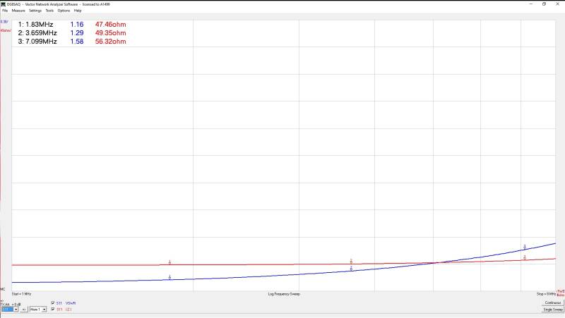
I also have to look at the phase. Because I don't have an oscilloscope for the time being, I had to do this in a different way.... the RX port of the combiner with the coax that normally runs to the shack connected to the VNA and the other port of the VNA connected to the center antenna. the port NE and SW terminated with 75Ohm.
after this I calibrated my VNA so that the phase after calibration came to 0°, then connected everything the same and then made a measurement on RX2 and according to that measurement there is a difference of 0.45°.
Negligible in my opinion but I want to check the measurement of that VNA(DG8SAQ) with an oscilloscope.
If I send a signal to the center port on both RX9's with a signal generator, then the output signal from both RX port's should be visible on the scoop and hopefully they will run parallel....
I knew that not everything would go smoothly, but I am already further in my project than I thought.
soon more :-)
29/11/2021
Yesterday I disconnected the second RX9 and measured everything.
Special attention has been paid to the phase and delay lines.
As you can see below I am on the NW port at -160.26° and on the SW port I am now at 161.35°.


Unfortunately at this point I also had to break down the antennas the standpipe I used was made to keep the finer antennas straight but not for the heavier ones which caused them to bend.
Working outside at the moment is very difficult all meadows are under water here, which has made it more of a swamp than a meadow.
This afternoon I'm going to buy some sturdier standpipes so that I can maybe put all the antennas back in the evening.
Yesterday also a new dog but that's on another page.
30/11/2021
We are another day further and the antenna feet have been changed to a heavier tube, today I have to do 1 more it got too dark last night to do it yesterday.
Both combiners have been re-measured and adjusted a bit so that I get closer to the correct phase and that they are both as close as possible.


At the moment I am about 1 ° of the correct phase discussed in the YCCC manual.
Apart from the antenna that still needs to be replaced, little will be done to the system today.
I am now looking around to buy some extra measuring devices.
The tests this morning at 160m and 80m are promising. The output of both RX's is better and more similar than before.
At 160m there was not much to experience this morning, at 80m I listened on SSB,
Combined my noise floor drops and I notice an improvement than the mono versions on stations from the USA.
especially the difference in noise level is already a step in the right direction.
We couldn't wait and I still had to replace a bolt per antenna so I made them all 50cm longer.
according to the YCCC manual I should now have a higher output, I can already say that I do not notice this.
The rest of the tests will take place this evening when 160m reopens.
01/12/2021
Another day further and did some extra tests.
We have put the coupling combiner on the workbench again.
I noticed that my relay didn't always respond when I wanted it ... it has since been replaced.
While I was still at it, I measured everything again.
Port RX1 and Port RX2 has a 70db suppression compared to the combi port.
Impedance Port RX1 and Port RX2 are identical around 49 Ohm the combi port is at 52 Ohm.
The whole system has a loss of 0.1db.
So I am now really sure that the problem is certainly not in the coupling combiner.
If the weather is good I will measure the coax of RX1 and RX2 and also measure with the VNA whether they both have the same length and while I'm at it I'll see how much loss that coax has for me
05/12/2021
A few results, as I have already reported above, I have to get both even better in terms of the output of the systems.


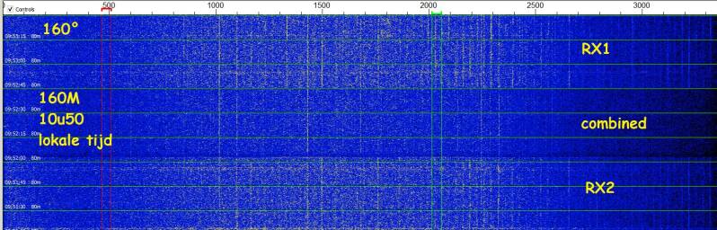
As you can see less noise on the combined version...
But I'm not there yet, I still have to check a few things with the necessary measuring equipment.
09/12/2021
RX2 is not in use at this moment.
We started by doing some testing in the shack with an oscilloscope.

After a tip from ON4TTT I first had to see if channel A and channel B on the same signal have the same result and it does as you can see. Now this oscilloscope is calibrated every 6 months. (work)
Before we connect everything to the oscilloscope you have to pay attention because the preamp works on 12v make sure you use a bias T before you connect it


Have tested all the preamps of the RX2 and they are perfect as they should be.
Above you see 2 measurements, the rest is identical.
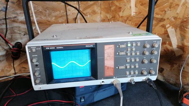
This is a measurement where you can see that both input and output signal match perfectly when I measure the output reversed.
Somewhere in the course of the week I will measure the other preamps of RX1 as well as the combiners and finally test both combiners linked to each other.
13/12/2021
Again a few days further and did some extra tests.... and this will also be the last one this year.
The first test was to measure again whether both coaxes that run from the shack to the combiners are identical.
Below you can see that measurement and as you can see they are almost identical in my eyes.
I now also see that I have a loss of 0.61db on 55m coax, now you always have that loss, but I think it is not too bad.


I already did the following test but now that they are both in the shack I wanted to check this one again.
everything connected to RX1 means, the coax that normally runs to the shack connected to the RX port of the combiner and the other side connected to the VNA, the other port of the VNA connected to the center port of the combiner and then first a calibration done.
After that calibration you will see as below that the phase will be almost at 0°.

If I have done that calibration on RX1, I can now do a measurement when I connect everything RX and see what the deviation is.
If both are equal, the reading on RX2 should also be close to 0°.
As you can see below, closer to 0° will be difficult.

We also did the measurement in reverse, namely calibrated RX2 and then do the measurement on RX1.
As you can see, there is a very small deviation, but it is so small that this will mainly
be due to the measuring instruments, which are not professional material for us.

The last tests for this season have been done,
The cause that RX1 has more output than RX2 has not yet been completely found, but that will come.
And now we will especially enjoy 2 RX9 circles
sometimes combined and sometimes one at 160m and the other at the same time at 80m.... or one on long path and the other on short path at the same freq....
Yes I know it's pure luxury.
next is already there" testing" again a reversible beverage
Create Your Own Website With JouwWeb