Added Value of Matched Preamplifiers and Coaxial Cables
1. Combined allocation of preamplifiers and coaxial cables
The allocation below is technically logical because it combines the optimum preamplifier gain pairs with the optimum coaxial phase pairs. The only preamplifier pair with a non-zero calculated gain difference, P3-P6, is assigned to coax pair C3-C6, which is one of the best phase-matched coax pairs across the measured bands. The remaining preamplifier pairs are equal within the display resolution of the oscilloscope measurements.
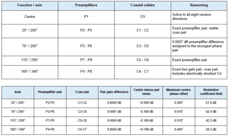
The last column is a simplified comparison between the centre vector and the mean of the outer pair. It is useful as an error-budget indication but is not a prediction of the true three-element array null.
2. What changes in the received signal in the real world?
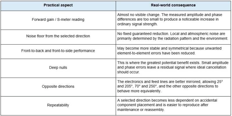
In a receiving array, the useful improvement is often not that the wanted station becomes stronger, but that an interfering station, local noise source or unwanted direction is rejected more effectively. A few extra decibels of rejection may be far more useful on a crowded or noisy band than a fraction of a decibel of additional wanted-signal level.
3. Effect on rejection, nulls and directional symmetry
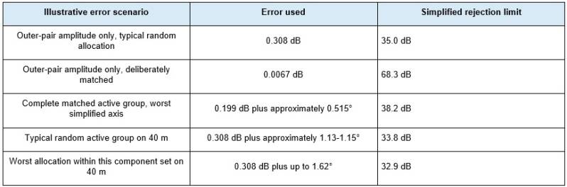
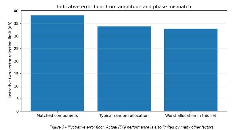
Outer-pair gain matching alone improves the amplitude-limited theoretical two-path cancellation limit from approximately 35.0 dB to 68.3 dB. This is a very large mathematical improvement, but it does not automatically produce the same improvement in the full array pattern. In the real three-element group, the centre-to-outer weighting becomes important; a maximum preamplifier spread of approximately 0.199 dB remains. The conservative combined error floor is therefore more likely to be set by the centre weighting and residual coaxial phase error.
The forward sum is almost unaffected. The matched phase errors are well below one degree, so the constructive summing loss is only a few ten-thousandths of a decibel. The practical gain is therefore not a stronger forward signal, but improved cancellation and more consistent pattern shape.
4. Comparison: deliberately matched, typical random and worst possible
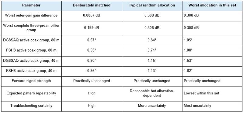
Because both the preamplifiers and the coaxial cables are already naturally close to one another, a random installation would probably still produce a useful array. Deliberate matching is nevertheless rational: it requires no extra hardware, only correct numbering and connection, and prevents a good component set from being used in an unnecessarily unfavourable combination.
5. Diagnostic and practical added value
- The component allocation is fully documented. A future fault can be traced to the exact preamplifier and coaxial cable assigned to each direction.
- A difference between two opposite receive directions is less likely to be caused by random preamplifier gain or cable length.
- When one preamplifier or coaxial cable is replaced, the replacement can be compared directly with its opposite partner.
- Independent confirmation of the coaxial phase by both the DG8SAQ and the FSH8 increases confidence in the measurement.
- If the complete chain later shows an abnormal result, the remaining search area is smaller: connector, Bias-T, relay, combiner path, element or environment.
- The present matching measurements provide a stable baseline for future maintenance and temperature checks.
6. What is not solved by this matching?
- The preamplifiers were accurately matched in amplitude, but their phase was not ranked using a calibrated VNA phase comparison.
- The coaxial matching used phase. Any small insertion-loss difference between cables was not included in the combined optimisation.
- Connector contacts, Bias-T units and transition cables may introduce additional amplitude or phase errors after installation.
- The combiner has its own amplitude weighting, relay paths and phase delays. Only a complete S21 chain measurement verifies the final result.
- The physical RX elements must also be electrically and mechanically equal. Differences in height, ground contact, environment and mutual coupling may be larger than the remaining component errors.
- Common-mode currents can change effective phase and pattern even when inner-conductor electrical lengths are perfectly matched.
- Local noise sources and signal arrival angles determine how much of the theoretical directional performance is visible on the air.
Component matching is the necessary foundation, not the final guarantee. The decisive final checks remain complete measurements of preamplifier + assigned coaxial cable + combiner path, followed by an on-air pattern test.
12. Recommended installation and verification procedure
- Permanently mark every preamplifier and coaxial cable with its number and assigned direction.
- Use P1 with C9 as the centre chain.
- Use P2-P5 with C1-C2 for 25°/205°.
- Use P3-P6 with C3-C6 for 70°/250°.
- Use P7-P9 with C5-C8 for 115°/295°.
- Use P4-P8 with C4-C7 for 160°/340°.
- Only swap the two sides within an opposite pair if complete-chain phase or physical direction logic requires it.
- After installation, first verify DC voltage and current, then measure S21 amplitude and S21 phase for every complete chain.
- Keep the present component measurements as the reference for future troubleshooting.
13. Final conclusion
FINAL ASSESSMENT: matching both the preamplifiers and the coaxial cables is technically worthwhile. It produces almost no noticeable increase in forward gain, but it balances the four opposite axes much more accurately and makes the complete RX9 more predictable. The main benefits are pattern stability, directional symmetry, the possibility of deeper rejection of unwanted signals and easier fault diagnosis.
Without deliberate matching, this particular component set would probably still work well because both the preamplifiers and coaxial cables are already exceptionally close. The result would, however, depend more on chance. Deliberate matching uses the best available combination without additional cost or mechanical modification.
The most accurate summary is therefore: matching hardly makes the wanted signal stronger, but it helps the array reject the unwanted signal as deeply, symmetrically and repeatably as possible.
Create Your Own Website With JouwWeb