Preamp measurements
1. Purpose of the measurement
The purpose of this measurement series is to determine whether the nine VE6WZ/YCCC element preamplifiers used in the RX9 array are sufficiently equal in DC behaviour, voltage gain and polarity. A phased receiving array is sensitive to unit-to-unit amplitude and phase differences. The investigation therefore covers both individual health and the optimum distribution of the nine measured units over one centre position and four opposite outer-element pairs.
2. Devices under test and traceability
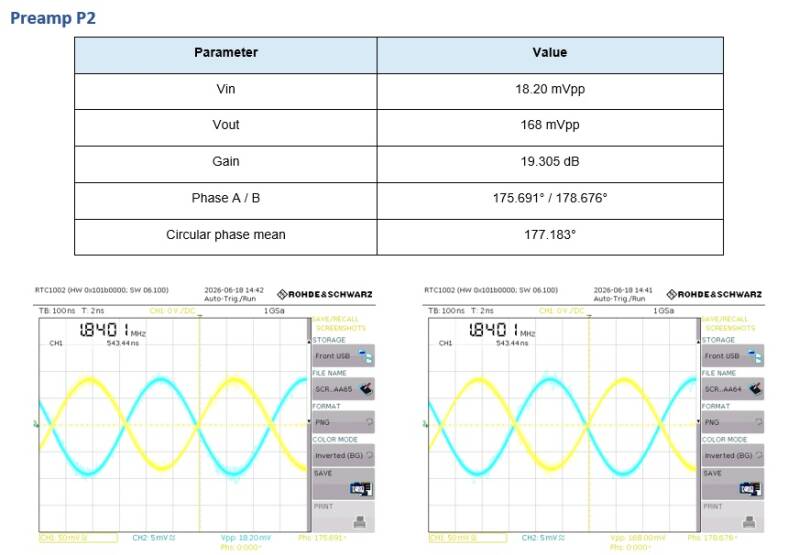
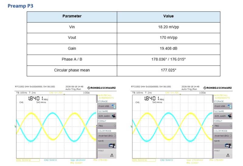
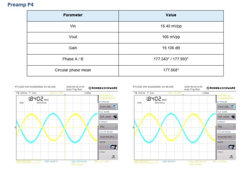
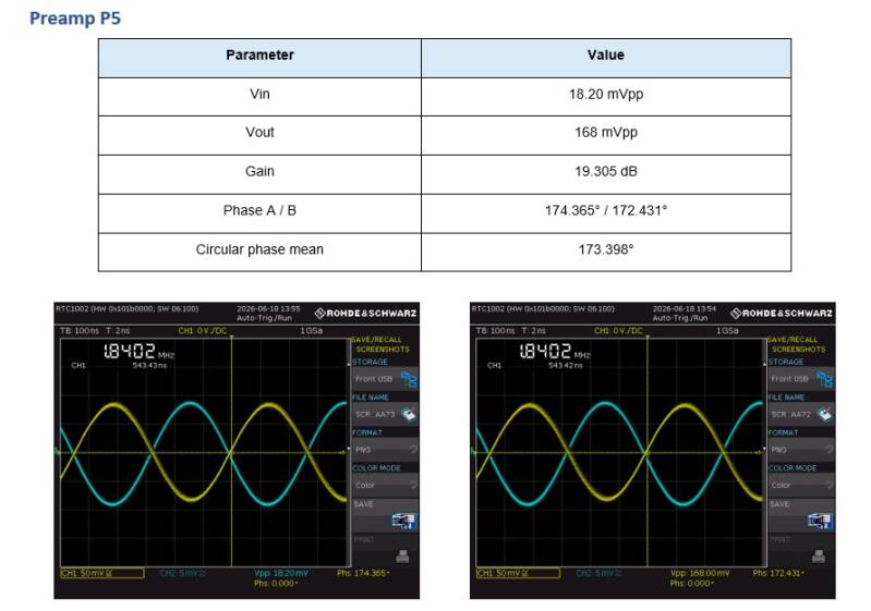
The population consists of nine individually numbered element preamplifiers, P1 through P9. Two RTC1002 captures are available for every unit: one capture clearly displaying the input Vpp and one clearly displaying the output Vpp. Both captures simultaneously show.
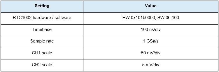
CH1 : preamplifier output, 50 mV/div.
CH2 : input/reference signal, 5 mV/div.
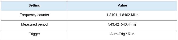
Nominal test frequency: approximately 1.840 MHz.
Bias-T supply voltage: 14.07 V.
Measured quiescent current: 34 mA per preamplifier.
2. Test equipment
DG8SAQ VNWA V2 used as a stable RF signal source.
Calibrated RTC1002 digital oscilloscope.
Calibrated Rohde & Schwarz FSH8
Calibrated Fluke multimeter for supply-voltage verification.
Bias-T used for simultaneous RF extraction and DC supply.
Identical coaxial cables and connections for all nine preamplifiers.
Nine VE6WZ/YCCC element preamplifiers from the same 9RX array.
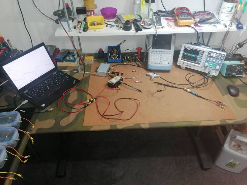

4. Test setup and settings
The VNWA output was connected to the terminal normally used by the RX vertical element. The preamplifier output passed through the Bias-T to RTC1002 channel 1. Channel 2 monitored the applied VNWA signal. This made input and output visible at the same time, allowing both voltage ratio and polarity to be assessed.
5. Measurement procedure
- Verify the Bias-T output and confirm 14.07 V with the Fluke meter.
- Connect the VNWA source to the antenna input of the preamplifier under test.
- Connect the preamplifier output through the Bias-T to RTC1002 channel 1.
- Connect the input/reference signal to channel 2.
- Keep source frequency, cables, Bias-T, probes and oscilloscope settings unchanged.
- Read Vin, Vout and the automatic phase value and save two captures.
- Repeat the identical procedure for P1 through P9.
- Calculate gain for each preamplifier from its actual measured Vin and Vout.
6. Calculation method
Linear voltage gain is calculated as:
Aᵥ = Vout / Vin
Gain in decibels is then:
GdB = 20 × log₁₀(Vout / Vin)
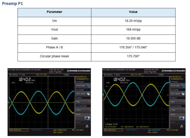
Example P1: Aᵥ = 168.0 / 18.20 = 9.2308. G = 20 × log₁₀(9.2308) = 19.305 dB.
For matching, the absolute gain difference of each opposite pair is used:
ΔGpair = |Gi − Gj|
A dB difference can be converted to relative voltage mismatch using 100 × (10^(ΔG/20) − 1).
7. Definitive amplitude and gain results
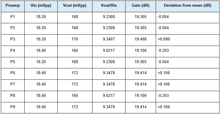
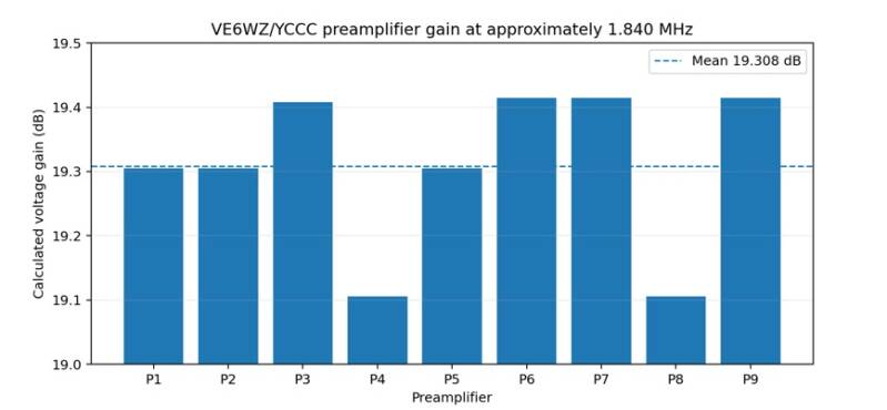
This may appear to be a large deviation, but it represents only the difference between 19.1 dB and 19.4 dB, namely the lowest and highest measured values.
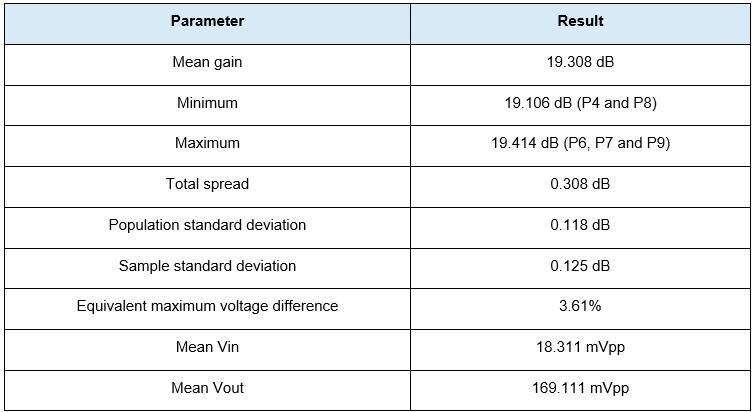
8. Statistical analysis
9. Phase behaviour and interpretation
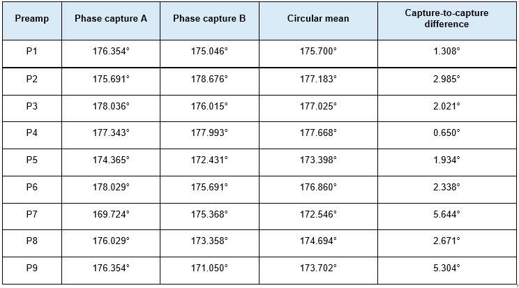
All nine preamplifiers show the expected inversion: CH1 and CH2 are approximately 180° apart. However, the two automatic phase readings of the same unit sometimes differ by several degrees while amplitude remains essentially unchanged. This demonstrates that the automatic scope phase reading at an input of only about 18 mVpp is not accurate enough to rank units by fractions of a degree.
The phase data are therefore a polarity and health check, not a precision criterion for final matching. A calibrated S21 phase measurement is more appropriate for accurate phase comparison.
10. Measurement uncertainty and limitations
- This is a relative comparison using one unchanged fixture; absolute broadband gain was not the primary objective.
- Displayed Vin values change in 0.20 mV steps and Vout values in 2 mV steps.
- Using half of the last displayed digit as a simple quantisation estimate (±0.10 mV and ±1 mV), the resulting gain uncertainty is approximately ±0.07 dB. Using a full display step gives about ±0.14 dB.
- The calculated 0.0067 dB difference between P3 and P6/P7/P9 is far below this practical resolution and must be interpreted as effectively equal.
- The total spread of 0.308 dB is clearly larger than one display step and is therefore more meaningful than the small differences within the high-gain group.
- The test applies near 1.840 MHz; equal broadband behaviour on 80 and 40 metres is not proven by this single-frequency test.
- The source and load impedances of the fixture are not completely identical to the final antenna environment, but the relative comparison remains valid because every unit was measured identically.
11. Matching objective for the 9-circle array
The RX9 uses one centre channel and eight outer channels. The outer channels form four geometrically opposite pairs. From the preamplifier-gain perspective, the primary matching objective is to make the two members of every opposite pair as equal as possible. The centre unit is then assessed by its proximity to the mean of the eight outer preamplifiers.
The optimisation is lexicographic: (1) minimise the largest pair mismatch, (2) minimise the sum of the four pair mismatches, and (3) minimise the difference between the centre preamplifier and the mean of the outer preamplifiers.
12. Number of possible matchings
With nine distinct preamplifiers, one centre unit is selected first. The remaining eight are divided into four unlabeled pairs. The number of unique pair partitions of eight objects is:
8! / (2⁴ × 4!) = 105
Because any of the nine preamplifiers can be the centre unit, the total is:
9 × 105 = 945 unique preamplifier matchings
For gain matching, the 945 unlabeled centre-plus-pair combinations are the technically relevant search space. The larger counts are wiring permutations of the same pairings.
13. Exhaustive matching calculation
All 945 possibilities were evaluated. For each candidate centre, the 105 possible pair partitions of the remaining eight units were generated. ΔG was calculated for all four pairs, followed by the maximum, sum and RMS of the four mismatches.
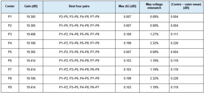
Only P1, P2 and P5 reach the global minimum. They have exactly the same measured gain. With any one of these three as centre, three outer pairs can be made exactly equal and only one calculated mismatch of 0.0067 dB remains.
14. All globally optimal solutions
There are exactly 9 globally optimal unlabeled matchings among the 945 possibilities: only 0.95% of the full search space. Assigning the four optimal pairs to four specific physical axes gives 9 × 4! = 216 equally optimal gain allocations. Allowing the two sides within each pair to be swapped gives 216 × 2⁴ = 3,456 complete wiring variants.
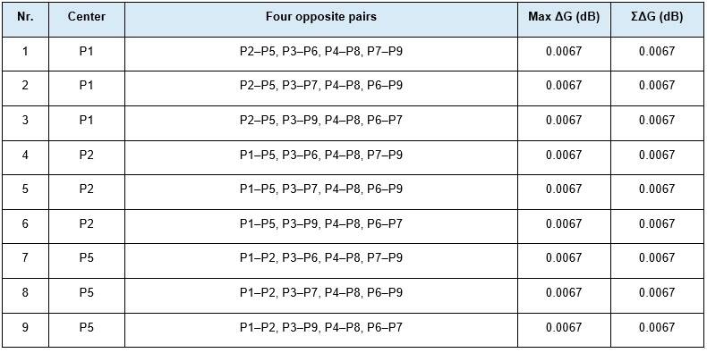
15. Recommended allocation
The allocation below is one of the nine global optimum solutions and is consistent with the adopted preamplifier numbering. It uses P1 as the centre unit and forms the four best opposite gain pairs.
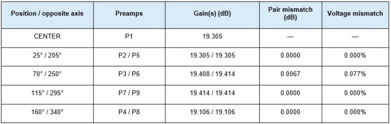
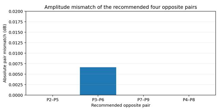
P2–P5, P7–P9 and P4–P8 are exactly equal according to the displayed Vpp values. P3–P6 differs mathematically by 0.0067 dB, corresponding to only 0.077% in voltage. This difference is far below the practical measurement resolution and must therefore be treated as equal.
With P1 as the centre unit, the mean gain of the eight outer preamplifiers is 19.309 dB. P1 differs from this mean by only 0.0042 dB, corresponding to approximately 0.048% in voltage.
Based on preamplifier gain alone, the four optimal pairs can be permuted freely among the four axes. Final physical direction assignment may later be combined with the separate coax phase data; those data are deliberately outside the scope of this preamplifier report.
16. Technical assessment
- All nine preamplifiers draw the same 34 mA quiescent current at 14.07 V; there is no DC outlier.
- All nine provide approximately 19.1–19.4 dB voltage gain near 1.840 MHz.
- Total spread is only 0.308 dB; no unit is defective or unsuitable.
- P4 and P8 form an exact low-gain pair.
- P1, P2 and P5 form an exact mid-gain trio; one is the optimum centre choice and the other two form an exact pair.
- P6, P7 and P9 form an exact high-gain trio; two form an exact pair and the third is paired with P3.
- P3 is only 0.0067 dB below P6/P7/P9 and is effectively identical within measurement resolution.
- All units invert phase; none shows reversed polarity or a gross phase defect.
- Oscilloscope phase is not stable enough to optimise placement by a few degrees; gain is the useful matching criterion.
17. Final conclusion
FINAL ASSESSMENT: all nine VE6WZ/YCCC element preamplifiers are electrically healthy and suitable for the RX9 array. The correct mean gain is 19.308 dB and the total unit-to-unit spread is 0.308 dB. An exhaustive evaluation of all 945 technically unique matchings produces nine global optimum solutions. The recommended choice of P1 as centre with opposite pairs P2–P5, P3–P6, P7–P9 and P4–P8 reaches the absolute minimum: three pairs are exactly equal and the fourth differs by only 0.0067 dB, far below practical measurement resolution.
I am not an expert. I carried out the measurements and analysed them, then entered all my findings into AI. The AI then generated and formatted this report. I have reviewed it myself, but there may still be a few errors in it.
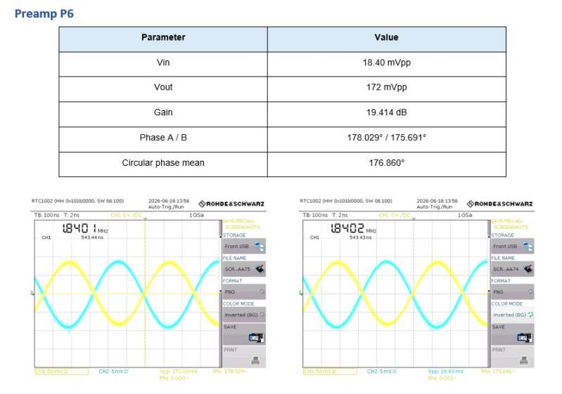
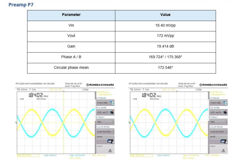
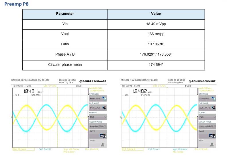
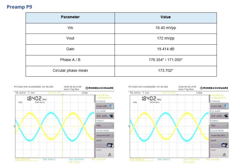
18. Definitive oscilloscope captures
Two original RTC1002 captures are shown for every preamplifier. The A/B order follows the filenames; depending on the capture, either Vin or Vout is the active Vpp measurement shown at the bottom.
Create Your Own Website With JouwWeb